1. http://www.c-sharpcorner.com/UploadFile/mahesh/GDIApplication10302009063434AM/GDIApplication.aspx
This article discusses vital concepts, including the life cycle of a graphics application. After reading this article, you should understand the basics of the GDI+ coordinate system, basic graphics structures used by GDI+, drawing surfaces, and how to write a graphics application using GDI+.
To write a graphics application, a good understanding of drawing surfaces and coordinates system is necessary. We will begin by discussing these concepts and how they are represented in GDI+. Then you'll learn step-by-step how to write a graphics application in the .NET Framework using GDI+. We will cover the following topics:
- How to add a reference to the GDI+ library
- How to get a drawing surface in the program
- How to create pens and brushes
- How to use pens and brushes to draw graphics objects
At the end of this article we will discuss some basic graphics structures and their members. The structures are used in examples throughout this article and include the following:
- Color
- Point and PointF
- Rectangle and RectangleF
- Size and SizeF
Drawing Surfaces
Every drawing application (regardless of the operating system), consists of three common components: a canvas, a brush or pen, and a process.
- The canvas is the space on which objects will be drawn. For example, in a Windows application, a Windows Form is a canvas.
- A brush or a pen represents the texture, color, and width of the objects to be drawn on the canvas.
- The process describes how objects are drawn on the canvas.
To draw graphics objects you need to have a pen or a brush, which defines the texture, color, and width of the drawing. For example, if you draw a line or a rectangle, you need to create a pen with a color and width.
The process component of the drawing application includes making a call to draw the line or rectangle on the form.
Each drawing surface has four common properties: width, height, resolution, and color depth.
- The width and height properties of a surface determine the size of the surface, and they are specified by the number of pixels horizontally and vertically, respectively.
- The resolution property of a surface is a measurement of the output quality of graphics objects or images in dots per inch (dpi). For example, as resolution of 72 dpi means that 1 inch of the surface holds 72 horizontal and 72 vertical pixels. For monitors and LCDs, the resolution is frequently specified in terms of the total number of pixels horizontally and vertically rather than a pixel density. Thus a monitor resolution of 1280x1024 means that the screen of the monitor can hold 1280 horizontal pixels and 1024 vertical pixels.
- The color depth of a surface is the number of colors used to represent each pixel.
Definition: PIXEL
A pixel is the smallest element that participates in the drawing process to display graphics objects or images on the screen. The pixel density is often represented by a value in dots per inch (dpi).
The quality of a pixel is directly proportional to the color depth. The Color structure represents a color in GDI+. It has four components: alpha, red, green, and blue. The RGB (red-green-blue) components of a color represent then umber of possible colors (see Figure below). Each component in the RGB has 256 (28) color combinations. Hence all three components of a GDI+ color represent 256x256x256 possible colors. The alpha component determines the transparency of the color, which affects how the color mixes with other colors.
To see the proper colors defined in the GDI+ color structure, a drawing surface must support at least a 24-bit color system (for the RGB components of a color structure), which means that each pixel of the surface must be able to hold 24 bits (8 bits each for the R, G, and B components, as noted already). Surfaces with less than 24 bits per pixel may not display graphics objects and images exactly as defined in a drawing application.
NOTE
The color depth of a surface is different from the color depth of a particular display device, such as a monitor or a printer. Most monitors can support over a million colors, and some printer may support only black and white.

FIGURE: Color components in GDI+
GDI+ provides three types of drawing surfaces: forms, printers, and bitmaps.
Forms as a Surface
When you write a Windows application that draws something on a form the forms acts as a drawing surface and supports all the properties required by a drawing surface.
Printers as a Surface
When you print from an application, the printer acts as a drawing surface. You can set a printer's resolution and color-depth, as well as the height and width of the paper.
Bitmaps as a Surface
When you create images in memory and save them as a bitmap, the bitmap functions as a drawing surface. You can set the image width, height, resolution, and color depth properties. Bitmap surfaces are commonly used for writing graphics Web applications. Drawing works a little differently in Web applications. For example, if you want to draw a line and a rectangle in a Web page using GDI+, you need to create an image, use this image as a surface for the line and rectangle objects, set its surface-related properties, and then send the image to the browser.
The Coordinate System
Understanding the coordinate system is another important part of graphics programming. The coordinate system represents the positions of graphics objects on a display device such as a monitor or a printer.
The Cartesian Coordinate System
The Cartesian coordinate system (shown in Figure below) divides a two dimensional plane into four regions, also called quadrants, and two axes: x and y. The x-axis represented by a horizontal line and the y-axes by a vertical line. An ordered pair of z and y positions defines a point in a plane. The origin of the plane is a point with x=0 and y=0 values and the quadrants divide the plane relative to the origin.

FIGURE: The Cartesian coordinate system
To find out which point falls in which quadrant, we compare the point's x- and y- positions relative to the origin:
Quadrant I: x>0 and y>0
Quadrant II: x<0 and y>0
Quadrant III: x<0 and y<0
Quadrant IV: x>0 and y<0
A point with positive x and y values will fall in quadrant I. A point with +y and -x values will fall in quadrant II. A point with -x and -y values will fall in quadrant III, and a point with +x and -y values will fall in quadrant IV. For example, a point at coordinated (2, -3) will fall in quadrant IV, and a point at coordinates (-3,2) will fall in quadrant II.
The Default GDI+ Coordinate System
Unlike the Cartesian coordinate system, the default GDI+ coordinate system starts with the origin in the upper left corner. The default x-axis point to the right and the y-axis points down. As Figure below shows, the upper left corner with points x=0 and y=0. Points to the left of x=0 are negative values in the x-direction, and points above y=0 are negative values in the y-direction.

FIGURE: The GDI+ coordinate system
Because the default GDI+ coordinate system starts with (x=0, y=0) in the upper left corner of the screen, by default you can see only the points that have positive z and y values. Objects with either -x or -y values will not be visible on the screen. However, you can apply transformations to move objects with negative values into the visible area.
GDI+ provides three types of coordinate systems: world coordinates, page coordinates, and device coordinates.
- The coordinate system used in an application is called world coordinates. Suppose that your application draws a line from point a (0,0) to point B (120,80), as showing in Figure below. If you don't apply any transformation, the line will be displayed at the right location. Now suppose you want to draw a line from point A (-40, -50) to point B (-10, -20). The line drawn using these two points will not be displayed on the screen because the GDI+ coordinate system starts at point (0,0). However, you can transform the coordinates such that (-40, -50) is the starting point at the top left corner of the surface.
- The new coordinate system is called page coordinates. The process of converting world coordinates to page coordinates is called the world transformation.

FIGURE 2.4: Drawing a line from point (0,0) to point (10,80)
- You can also control the actual size of graphics objects. For example, if you want to draw a line in inches instead of pixels, you can simply draw a line from point A (1,1) to point B (1,2), thereby creating a line that is 1 inch long. The new coordinates are called device coordinates. The process of converting pages coordinates to device coordinates is called the page transformation.
2. Pro .NET 2.0 Graphics Programming
by Eric White, Apress © 2005.
In GDI+, there are four basic types of transformations:
· Scaling transformation: This type of transformation changes the size of the result. So if you apply a scaling transformation that increases the size of the subsequent drawing operations, the result when you draw the letter A appears to be larger, as shown in Figure 8-2.
· Translation transformation: This type of transformation has the effect of shifting the results of subsequent operations a specified distance left or right, and up or down. So, if you apply a translation that shifts down and to the right to your drawing surface, and then draw the letter A, the result might look like Figure 8-3.
· Rotation transformation: This type of transformation has the effect of rotating elements through a specified angle about a specified point. Figure 8-4 shows an example (although, as you'll see later, the example isn't quite as straightforward as it looks).
· Shearing transformation: This type of transformation reminds me of how a cartoonist conveys an image of a car moving fast by drawing the car leaning backwards. Mathematically, a shear is a transformation that turns a rectangle into a parallelogram. Figure 8-5 shows an example with the same letter A.
· World coordinates: The world coordinate system is the one that you reference in your application. Whenever you pass coordinates to any drawing function, you express those coordinates in the world coordinate system. Any transformations that you apply transform your coordinates from world coordinates to page coordinates.
· Page coordinates: The configuration of the page coordinate system determines the units in which you draw. Its origin is at the upper-left corner of the client area. By default, you express page coordinates in terms of pixels. If you change the unit of measure for the page from pixels to, say, inches, this conversion takes place to give device coordinates.
· Device coordinates: The device coordinate system is based on pixel coordinates, which, like page coordinates, are relative to the upper-left corner of the client area (or the upper-left corner of the printable area of the page).
So, when GDI+ outputs to a device (like a screen) there are two coordinate conversions that take place: a world transformation, which converts from world coordinates to page coordinates, and a page transformation, which converts from page coordinates to device coordinates.
You might be drawing a very intricate diagram that you expect to look acceptable when it's drawn very small, perhaps using anti-aliasing, and you also want it to look good when you scale up the drawing, so that it fills a large window. To facilitate both of these situations, coordinates are often expressed with floating-point precision in the world coordinate system.
By default, the page coordinate system unit of measure is Pixel, which is the most useful unit for making custom controls, as noted in Chapter 2. However, for other applications, such as writing code that draws engineering diagrams, you may want to express coordinates in units other than pixels. If you set the page coordinate system to another value—such as Inch, Millimeter, or Document—your coordinates are then expressed in the associated unit of measure (inch, millimeter, or 1/300 inch, respectively).
The device coordinate system is always pixel-based. This is related to the fact that all drawing surfaces in GDI+ are raster-based.
Units of Measurement
In this section, we will take a closer look at measurement units. This actually is part of the larger topic of page transformations and the world coordinate system, which was introduced in Chapter 8. Here, we'll examine the measurement units in relation to printing.
Painting vs. Printing Measurements
By default, when painting in response to a Paint event, the graphics unit is set to ensure measurements are in pixels for drawing shapes and images (though not for text fonts, as you'll see in this section). So, for example, the following code will display a square that is 100 pixels by 100 pixels:
private void PaintDocument(Graphics g)
{
    ...
    g.PageUnit = GraphicsUnit.Pixel;           // can omit this line
                              // line as Pixel is the default anyway
    Rectangle cr = new Rectangle(new Point(10,90), new Size(100, 100));
    g.DrawRectangle(Pens.Blue, cr);
}
Using pixels as a measurement is often extremely convenient for displaying to the screen, because a pixel is the smallest unit that can be drawn on the screen. By specifying a line width for a horizontal or vertical line as an integer number of pixels, for example, you know that you are specifying a line width that can be drawn exactly, resulting in a clear image on the screen that can be drawn without aliasing.
Unfortunately, when it comes to printing, measuring sizes in pixels causes problems, because a pixel is considerably smaller on a printer than it is on the screen. On the screen, the preceding code will result in a square with sides of approximately 1 inch, depending on the exact resolution of the monitor. But many printers come with resolutions of over 1000 DPI (dots per inch, the number of pixels per inch). If you use the preceding code to print a square on the printer, the square will still have sides of 100 pixels each, but on a printer with a resolution of 1200 DPI, this will be less than 0.1 inch! So, if you use pixels for your measurements, it becomes a lot harder to write applications whose printouts look the same as the graphic displayed on the screen.
Fortunately, we can get around this by setting the Graphics.PageUnit property.
Setting the PageUnit Property of the Graphics Object
The Graphics.PageUnit property allows you to use measurements in some unit that remains roughly the same on the screen and printer. You can set it to any of the values listed in Table 9-2from the GraphicsUnit enumeration (which is part of the System.Drawing namespace).
Table 9-2: Graphics.PageUnit Values
- Pixel: Smallest unit into which an image can be broken down; typically, 1/96 inch on a display device, and anything from 1/300 to 1/1000 or less on a printer
- Inch: An inch
- Display: 1/96 inch
- Point: A standard point as traditionally used by printers, equal to 1/72 inch
- Document: 1/300 inch
- World: A unit determined by the Graphics object's world transformation
The following code will draw a square with sides roughly 1 inch, regardless of whether it is drawn to the screen or the printer:
private void PaintDocument(Graphics g)
{
    ...
    g.PageUnit = GraphicsUnit.Inch;
    RectangleF cr = new RectangleF(new Point(0.4f, 0.9f),
                                   new Size(1.0f,1.0f));
    g.DrawRectangle(Pens.Blue, cr);
}
The rectangle will be located roughly 0.4 inch horizontally and 0.9 inch vertically from the top left corner. Note that because we are using inches, we need to express measurements in fractional numbers, and hence need to use a RectangleF object rather than a Rectangle object.
An unfortunate anomaly is that screen measurements are not always precisely correct. By default, all screen resolutions are defined to be 96 DPI (you can check this in the Settings tab of your windows desktop Properties dialog box, by clicking the Advanced button). However, different monitors have different sizes, and so they don't always display 96 pixels to the inch. Therefore, that measurement is only approximate. On the other hand, the computer is able to query a printer for its precise DPI, so measurements do normally come out exactly as specified on the printed page.
There are three separate areas in which you need to pay particular attention to the PageUnit property of the Graphics object: when you're drawing lines and filling shapes, drawing text, and drawing images.
Units for Drawing Lines and Filling Shapes
Coordinates that you pass to drawing methods are in the units of the PageUnit property. As mentioned, the default setting for PageUnit is GraphicsUnit.Display. By default, all coordinates are expressed in 1/96 inch.
One point that may not be immediately obvious is that pen widths are also expressed in the same units. If you use a pen width of 1, this means that the pen width will be 1/96 inch. If your printer has a resolution of 300 DPI, the pen will be about 3 pixels wide.
Units for Drawing Text
With Font objects, the Font.Unit property is the GraphicsUnit for text drawn with the font. This means that you can use one scale for drawing lines and filling shapes, and another scale for drawing text. Thus, you could conceivably have a method that draws some text at a position expressed in the units stored in Graphics.PageUnit, although the actual size of the text drawn is based on the units stored in Font.Unit.
The default value for Font.Unit is GraphicsUnit.Point, which is defined to be 1/72 inch. If you let the Graphics.PageUnit property remain set to GraphicsUnit.Display, and you let the Font.Unit property remain set to GraphicsUnit.Point, you can accurately predict how your drawing operations will affect the drawing surface.
Alternatively, you could set the Graphics.PageUnit property to GraphicsUnit.Inch, and also set the Font.Unit property to GraphicsUnit.Inch. In this case, all operations use the same unit of measure, which may simplify your drawing code. If you use this technique, there is one point to remember: pen widths will also be expressed in terms of inches. If you create a pen with a width of 1, this means that your pen will be 1 inch wide! However, this is easy to rectify, since you can express pen widths as floating-point numbers. If you set the pen width to 1/96, you will get the same results as if you had left Graphics.PageUnit set to GraphicsUnit.Display.
Drawing Using Inches
In this section, we will develop a sample application, called RulerPrintingExample, which illustrates use of the Inch as the graphics measurement unit. Here's what we need to do when using this technique.
- Set the Graphics.PageUnit property to GraphicsUnit.Inch. We do this both when printing and when drawing to the screen.
- Set the pen width to 1/96 inch. As noted earlier, when printing, this has a nearly identical effect as using a pen width of 1 when the Graphics.PageUnit property is set toGraphicsUnit.Device. However, because the screen is defined as having a resolution of 96 DPI, this results in creating a pen with a width of exactly 1 pixel. This removes any chance of aliasing; or if anti-aliasing is turned on, this removes the possibility of antialiasing artifacts.
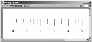
This example actually draws a ruler, which will appear roughly the same when drawn in a window or printed to a page. I say "roughly" because, as previously noted, depending on your monitor, the measurements may not be exactly correct on the screen, although they will be on the printed copy.
The code for this example is almost identical to that for the earlier SimplePrintingExample. In fact, the only difference is in the implementation of the PaintDocument method:
private void PaintDocument( Graphics g )
{
    g.PageUnit = GraphicsUnit.Inch;
    g.SmoothingMode = System.Drawing.Drawing2D.SmoothingMode.AntiAlias;

    float offset = .75f;
    Pen p = new Pen(Color.Black, 1.0f / 96.0f);
    for (float rule = 0; rule <= 5.0f; rule += .25f)
    {
        float x = offset + rule;
        float len;
        if (rule == (int)rule)
        {
            String s = ((int)rule).ToString();
            len = 0.5f;
            System.Drawing.Font f =

                  new Font( "Times New Roman", 0.25f, GraphicsUnit.Inch );
            StringFormat sf = new StringFormat();
            sf.Alignment = StringAlignment.Center;
            RectangleF mr = new RectangleF(x - .25f, 1.5f, .5f, f.Height);
            g.DrawString(s, f, Brushes.Black, mr, sf);
        }
        else if (rule * 2 == (int)(rule * 2))
            len = 0.375f;
        else
            len = 0.25f;
        g.DrawLine(p, x, .75f, x, .75f + len);
    }
}
private void Form1_Paint(object sender, PaintEventArgs e)
{
 Graphics g = e.Graphics;
 PaintDocument(g);
}
Running the RulerPrintingExample application results in the ruler appearing in the window, as shown in Figure 9-7.

The print preview results look like Figure 9-8.


0 comments:
Post a Comment